258 I6 and 304/360/401 V8 in CJ and FSJ
One of the most confusing aspects to tuning up an engine from the late 1970’s and 1980’s is all the early attempts manufacturers made to improve emissions with various vacuum-operated devices. In some cases (especially early-mid 1980’s), it almost looks like they designed the system by simply throwing a handful of spaghetti at the engine and saying, “Route the hoses like that.”
The best way to understand where everything goes is to get a copy of a factory service manual (FSM/TSM). Two good sources of these manuals are Amazon.com and Z&M Jeeps. Since these are pretty expensive (but worth it!), I’ve scanned a couple vacuum diagrams from my 1977 TSM and my 1974-80 parts manuals. I’m sure this collection isn’t complete.
EGR (Exhaust Gas Recirculation)
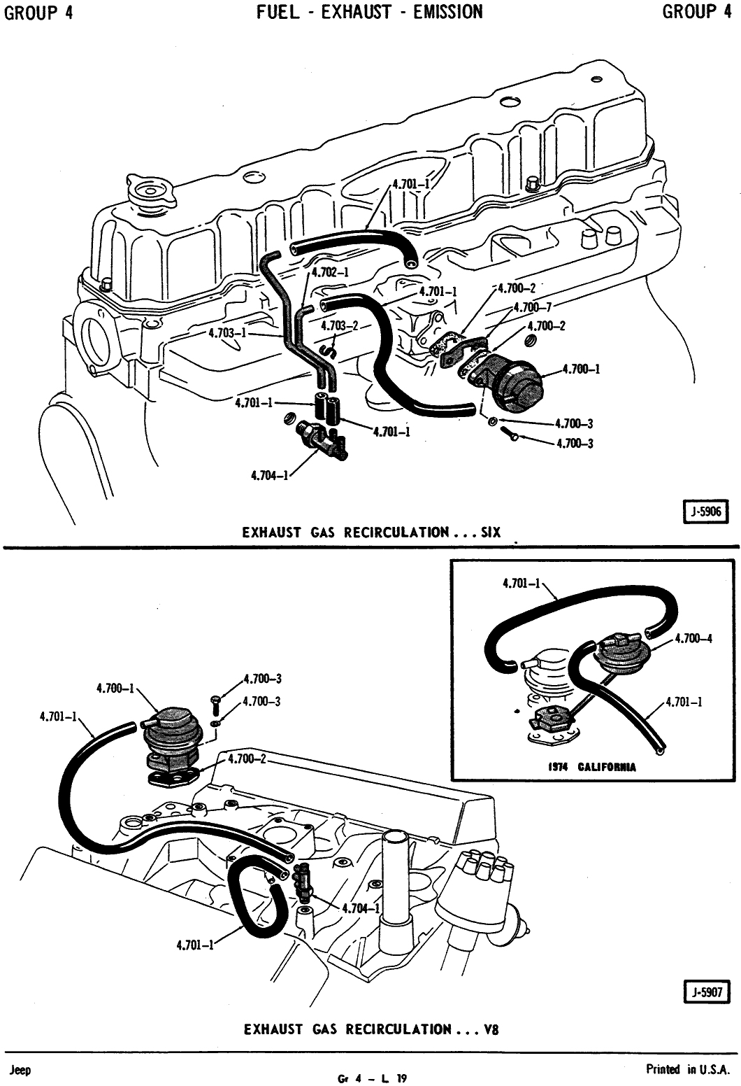 The purpose of the EGR port is to feed exhaust gas from the exhaust system back into the intake air flow whenever the coolant temperature is high enough and the ported vacuum is also high (ie, not during startup and only during heavy loads or hard acceleration). This decreases the engine temperature, which in turn decreases the emission of harmful nitrous oxide (NOx) gases. Reduced temps will reduce pinging, which will in turn allow you to advance your timing farther for better power throughout most of the RPM range. By diluting your intake charge with exhaust gas, the EGR will reduce your peak horsepower at higher RPM’s, but it will not adversely affect power under normal driving conditions. In fact, with the base ignition timing properly set, the EGR will allow for increased power at low- and mid-range RPM’s. If you use the engine for drag racing, then disabling the EGR is probably a good idea. For any other use, you’re better off making sure it works. Edelbrock makes Performer intake manifolds
 that come either with or without an EGR port.
The above image is the vacuum diagram for both the I6 and V8 engines. This was the same throughout the 1974-80 model runs for all Jeep models. If your EGR vacuum line has a red & blue delay valve in it, the blue side should point toward the EGR valve and the red side should point toward the CTO switch.
PCV (Positive Crankcase Ventilation)
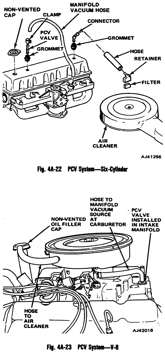 The crankcase on an engine will slowly build up positive pressure. This pressure must be released in a control manner to prevent the seals (most likely the oil pan seal) from blowing out. Some engines simply vent this pressure to the atmosphere using a breather cap on one or both valve covers. Since the vapor that’s vented contains nasty chemicals in addition to air, the environmentally-polite method is to vent these vapors back into the intake air flow. Jeep engines do this via a large (3/8″ or larger) vacuum fitting at the base of the carburetor. There is also a similar-sized hose that runs from the air filter to the oil fill cap (V8) or the front of the valve cover (I6).
The above image is the vacuum diagram for both the I6 and V8 engines. This was the same for all Jeep models, at least in 1977.
Fuel Vapor Storage Canister
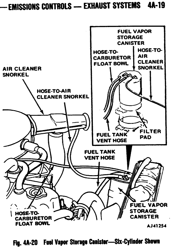 When it gets hot outside, the and and fuel vapor inside your gas tank expands. This excess pressure must go somewhere to prevent your tank from rupturing. Most older vehicles simply vent these vapors into the atmosphere through the filler cap. These caps use a valve that only opens when the pressure reaches a certain level. If the valve in your cap seizes shut, it’s time for a new cap. Newer vehicles (starting first in California, and later in all states) instead vent these vapors into — you guessed it — the intake air flow via a charcoal canister.
The above image is the vacuum diagram for both the 1977 I6 engine. This system first arrived in California FSJ and all CJ models, and was later added to 49-state FSJ’s.
Distributor Vacuum Advance
Most distributors from this era have several simultaneous methods of advancing the ignition timing. Base timing (the lowest amount of advance ever achieved) is usually set around 8-12 degrees BTDC. In addition to this, spring-loaded centrifugal weights will further advance the timing (as much as a dozen or two degrees) as the engine speeds up. The third, and most complicated method, is the vacuum advance. There are several different methods that Jeep employed to implement the vacuum advance feature, but it essentially works like this: A CTO (coolant temperature override) switch uses engine coolant to sense when the engine has warmed up. When it’s cold, the distributor is advanced using manifold vacuum, so the ignition is advanced farther when idling than it is under load. When the engine warms up, the distributor is advanced using ported vacuum, so the ignition is advanced farther under load than it is at idle. When using a 3-port CTO switch, the center port is common; the outer port is open when cold, and the inner port is open when hot.

")
")
The first image above is the vacuum diagram for both the 1974-80 I6 engine. The second and third images are the vacuum diagram for both the 1974-80 V8 engines of various configurations. In these V8 diagrams, the vacuum line to the base of the carb on the manifold actually indicates ported vacuum, not manifold vacuum. Yes, it’s confusing. Also, in these diagrams “10-20-40” and “10-25-45” indicate FSJ’s, while “80” indicates a CJ. “E/CALIF” means “except California,” while “CALIF” indicates a California-only model. “LHDC” indicates “less (without) heavy duty cooling” package, while “WHDC” indicates “with heavy duty cooling.”
Other references
There are a few other diagrams out on the Net that are also useful.
Amazon.com sells factory service manuals for lots of different Jeep models at great prices.
These two are for a 49-state 6-cyl 258, auto tranny, with and without heavy duty cooling. Judging from all the smog stuff, I’d say it’s probably for an early-1980’s Jeep.
Here is another scan from a similar manual detailing the vacuum diagram for a 1979 California V8 FSJ with auto tranny and heavy duty cooling.
Here is another set of scanned pages outlining the vacuum routing for mid-1970’s Jeep engines.
Here is a poor-quality scan of the V8 vacuum diagram from a 1984-85 FSJ manual.
Here are two more poor-quality scans of the V8 vacuum diagram from a 1989 V8 Grand Wagoneer with heavy duty and light duty cooling packages.
Here is another scan detailing the 1978 EVAP (charcoal) canister ports.
Here is a scan detailing the AIR injection pump setup.
And of course, there’s always Tom Collins’ site, which contains scans from TSM’s from several different years. It’s geared toward FSJ’s, but will mostly apply to CJ’s, too.
In the lower right corner of Joe Gorfinkle’s site, you’ll find lower-resolution scans from a 1976 TSM of much of the info that I scanned from my ’77 TSM above.
[Last updated 12 Aug 2011]
This is the best site to address the vacuum tubing on jeeps!
Very grateful you did this ! The j-10 thanks you as well.
What do I need for vacuum hoses using a DUI distributor in a Holley EFI injection system 84 CJ 7 258