
Ever since I rebuilt the AMC 401 V8 on my ’77 Jeep Wagoneer, the gas mileage just hasn’t been as high as it should be. I tried several things to fix it with limited success, but eventually decided that maybe the stock ignition system could use some help. To that end, I bought a used MSD 6T ignition control box along with a rev limiter and adjustable timing control module from a friend.
Normally, installing an MSD ignition on a vehicle this old isn’t too hard. You just remove the entire stock ignition control box and drop the MSD in its place. My setup was complicated somewhat because the MSD doesn’t work with the Prestolite distributor that Jeep used from ’75-77. In order to use the MSD box, I had to replace my distributor with either a points-style Pertronix distributor or a newer magnetic pickup distributor. I chose the cheap route, and yanked the Motorcraft distributor from my ’78 Wagoneer parts truck.
The grand plan for this upgrade included several points:
- Replace the stock ’75-77 Prestolite distributor with a stock ’78-91 Motorcraft distributor.
- Replace the stock Prestolite ignition control box with an MSD 6T ignition control module.
- Install the MSD 8680 Adjustable Timing Control module to allow adjusting the ignition timing within a 15-degree range on a running engine from the driver seat.
- Do the infamous “TFI upgrade,” which involves replacing the stock can-type coil with a Ford TFI coil, replacing the stock Motorcraft distributor “small” cap/rotor with a “big” cap/rotor, and replacing the spark plug wires with new ones to match the different terminal type on the new distributor cap.
The first step must be done before either the second or fourth will work, since neither is compatible with the Prestolite distributor. MSD recommends waiting to install the timing control until after the main ignition control module is installed and working. There is a small wiring change required to do it this way, but it definitely simplifies the process. Performing the first two steps simultaneously is much easier than trying to retrofit the entire Motorcraft control module into an older Jeep, only to rip it out again when the MSD goes in.
Installing the MSD 6T and Motorcraft Distributor
I fretted over this swap for a while, mainly because making irreversible (or difficult-to-reverse) changes of any real magnitude always makes me a little nervous. It turned out to be much easier than I anticipated.
Because my engine bay is somewhat prettier than most (though still far from show quality), I didn’t want to drop an ugly, corroded distributor into it. I spent a few hours with a Dremel tool and some white rouge polishing abrasive to give the visible portion of the distributor body a near-mirror finish, just like I’d done with my thermostat housing. Pretty engines always run better, right?
Before you do anything with the ignition wiring, you MUST disconnect the negative terminal from your battery to avoid any unwanted shocks. I removed my entire battery from the vehicle because it made it easier to access the rats nest that was my wiring harness.
’77 Wagoneer TSM
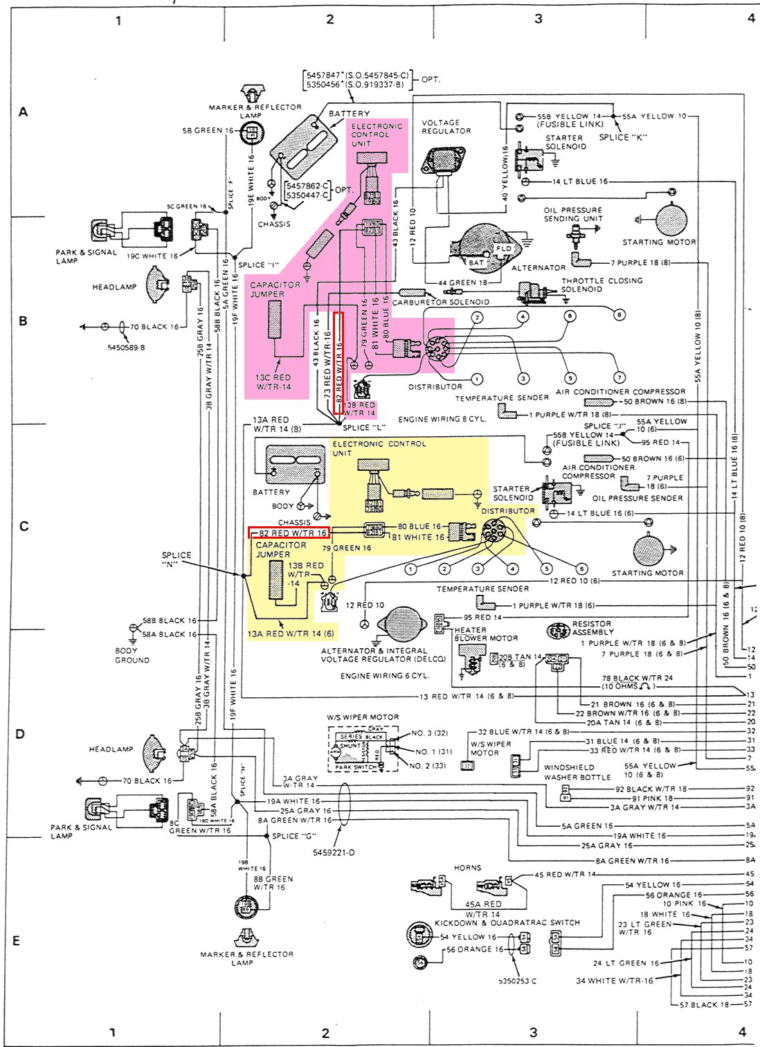
The first real step was to decipher and remove the stock control box and associated wiring. There were two metal boxes bolted to my passenger side inner fender. The one with the 3-wire connector right on the box is the alternator voltage regulator — leave that one alone. The ignition module is the one with the 4- or 5-wire connector at the end of a 6″ pigtail. The wiring harness between my ignition module, coil, and distributor may not have been stock (it was pretty hacked up), so I’m not sure how much my description will help. In order to remove this harness, I had to unplug it from the control box, the distributor, and the coil. The only remaining connections were to my tach (something I spliced in last summer) and a red 16 awg wire with a white tracer that provides switched 12V power. On my harness, this was connected via a bullet connector to a wire just 8″ from the coil. On my Jeep, what this left behind was a distributor with no wires connected (soon to be removed as well), a coil with no wires connected and no ballast resistor (the resistor was part of the wiring harness), a red power wire dangling free, and a green tach wire dangling free. I didn’t have to cut or splice any factory wires to do this upgrade, which was nice. In this page from my ’77 TSM, the pastel blocks indicate the components that need to be removed and/or disconnected (pink for V8; yellow for I6). The red box highlights the wire that will supply 12V switched power.
The next step was to remove the Prestolite distributor and replace it with the Motorcraft one. Before removing the distributor, you need to carefully mark the position of the #1 cylinder and the position of the rotor (pushed as far counter-clockwise as possible, since there’s a little play in it). To do this, I placed some masking tape on the radiator hose and on the P/S belt, then marked the appropriate locations on those tapes with a pen. That would normally (see below) allow me to line up the new distributor to approximately the same position. It would let it run well enough to start the engine, after which you’ll need to set the timing to the exact desired value with a light.
Removing the distributor is just a matter of removing the bolt (9/16″ head) and bracket at the base of the distributor. Because the cam gear is helically cut, the rotor will rotate about 30 degrees counter clockwise when you pull the distributor out of the timing cover. If your new distributor doesn’t already have one, be sure to move the thin gasket from the bottom of the mounting flange on your old distributor over to your new one. Before installing the Motorcraft distributor, you should probably slather engine assembly lube all over the gear teeth to keep them lubed until the running engine can get oil to them. When inserting the new distributor, remember to first rotate the rotor about 30 degrees CCW of where you want it to end up after it’s fully inserted. The oil pump drive shaft has a slot that the end of the distributor fits into. It’s possible that this shaft will rotate slightly during the distributor removal or installation, in which case you’ll need a long (6″) flat-blade screwdriver to stick down into the slot and turn the shaft so that it lines up again.
The first noteworthy problem that I ran into was that the vacuum advance hose nipple on the Motorcraft distributor stuck out about 3/4″ farther than the one on the Prestolite. I had the Prestolite nipple pointing straight forward, but that won’t work with the Motorcraft because the radiator fan will hit the vacuum hose. I therefore had to rotate the distributor about 60 degrees counter clockwise, making sure to rotate the rotor location along with it. The important thing here is the angle between the #1 terminal and the rotor, not the actual location of either one. In order to keep the relative angle the same, I took a 4″ square piece of paper, cut a small sight hole in the center so I could place it at the center of the rotor, and then drew lines out from the center to mark the location of the rotor and the #1 cylinder. I could then rotate the distributor and this paper any direction I chose and still match the rotor to the distributor’s #1 terminal position.
You’ll have to use the aforementioned screwdriver to rotate the oil pump drive shaft the same amount (unless it’s exactly 180 degrees), otherwise the distributor won’t seat all the way into the timing cover. Once the distributor is installed with the rotor as close as possible to the old position (relative to the #1 terminal location), reinstall the clamping bracket. Leave the bolt just loose enough that you can easily turn the distributor body by hand, but not so loose that it will wiggle around all by itself. You’ll need to rotate it when you fine tune the timing later on.
The next step was to mount the MSD 6T control box and hook up the wires. Mounting should easy — just find an open location on the fender where all the wires will reach, drill holes in the fender using the mounting bracket as a template, and attach the control box with sheet metal screws. It turned out to be the most time consuming part of the install, though, since I had to work around the existing stuff in the engine bay and still make sure all the wires would reach their intended destinations. I ended up moving the alternator regulator rearward about 12″ and mounting the MSD 6T on the flat area where the regulator and the Prestolite box used to sit. Sitting here, I was able to re-use an existing threaded hole in the fender well and drill two new ones. The lower front corner of the box isn’t screwed down, but it sits pretty solid with just three corners secured. Since clearance with the battery prevented me from using the 1″ tall rubber mounts supplied with the MSD (mounting it about 1″ farther rearward would have allowed this), I stuck some 1/4″ thick foam rubber weatherstripping to the bottom of the MSD box before I screwed it down. This seemed to do the job.
When I install the timing control box, it will be located on the rear part of the fender well right beside the hood hinge and in front of the heater blower motor. That should allow the 7′ long control cable to run through the firewall and be located inside the glove box.
The wiring is also pretty simple. I’ll describe it first without the timing control or rev limiter, since that’s the configuration that will match most people’s setups with the more common 6A and 6AL control boxes.
MSD 6T diagram
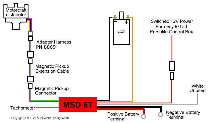
The diagram from MSD’s web site that you want to follow is for the Ford Duraspark using a magnetic pickup trigger. This is one of a dozen or so diagrams listed in the full instruction booklet that comes with the MSD 6 series control boxes. I recommend getting the MSD 8869 wiring harness that allows you to plug your Motorcraft distributor directly into the magnetic pickup terminal of the MSD control box without splicing any wires. It costs about $10 from any MSD reseller, which includes most large auto parts stores. Here’s the breakdown of which wires go where, following this diagram:
- The distributor’s wiring connector plugs into the 8869 adapter harness, which in turn plugs into the magnetic pickup connector (small, 2-wire, rectangular connector) on the MSD control box. The MSD diagram shows the wires from the magnetic pickup connector spliced directly into the wires from the distributor, but neither the splices nor the 8860 harness are necessary if you get the 8869 harness instead.
- The heavy gauge red wire on the control box goes to an always-on 12V source. I connected mine directly to the positive battery terminal, but another good spot would be the same terminal on the starter solenoid that the positive battery cable connects to. In fact, I may move it there to make the installation cleaner.
- The heavy gauge black wire on the control box goes to a good chassis ground or directly to the negative battery terminal. I connected mine directly to the negative battery terminal, but another good spot would be the upper A/C bracket mounting bolt, which is where the factor connected the other end of the negative battery cable.
- The thin gauge red wire on the control box goes to a 12V source that’s switched on with the ignition key. I used the same red wire that I unplugged from my old coil wiring harness. Prior to removing my battery, I tested this wire with a voltmeter to verify that it was indeed switched and that it was indeed providing 12V, since you don’t want to use the resistor wire that some Jeeps connected to their coils.
- The thin gauge black wire from the control box goes to the negative terminal on your coil. The stock Prestolite coil has threaded studs on the coil terminals. These studs are 5mm with a 0.8 thread/mm pitch. Yes, they really are metric, not #10-32 screws. I used some nuts and ring terminals to secure the wires in place. You could also hack up the old factory harness and splice the MSD wires into that if you wanted to.
- The orange wire from the control box goes to the positive terminal on your coil. These orange and black wires should now be the only wires connected to your coil. The MSD diagram shows the old coil connector in the diagram, but that’s only recommended as a good source for 12V switched power. It should not be hooked up to your coil under the new setup.
- The white wire from the control box is unused in this basic configuration, and should be taped off.
- If you have a tachometer (usually controlled with a green wire), you can plug it directly into the spade connector on the end of the control box next to the magnetic pickup trigger. Do NOT splice it into the negative coil wire like you would under the stock setup, since the multiple sparks produced by the MSD will really confuse your tach.
By now, the distributor, coil, MSD control box, and related wiring are almost completely separate from the rest of the Jeep’s wiring harness. The only wires connected to the old harness are the switched 12V power and (optionally) the tachometer. This is the way it was before the upgrade, too, but it wasn’t obvious because so much of the wiring was hidden inside that split-loom wire protector.
You should now be able to reconnect your battery and fire up the engine. If you had to swap in a new distributor, you should have a timing light hooked up and ready so that you can fine tune the timing immediately after the engine starts. Backfires are a Bad Thing(tm). If it doesn’t start, it’s probably because your timing is too far off thanks to the distributor swap. Try to have a helper turn the key while you monitor things with a timing light. If you can’t get a reading at cranking speed, try twiddling the distributor position 5-10 degrees to find a position where it will start, then fine tune it with the light.
My Wag fired right up with the new MSD control box and Motorcraft distributor. Base timing (at idle speed with the vacuum advance hose disconnected and plugged) was only a couple degrees off. I set it to 9 degrees BTDC. Now that I knew it was running OK, but before the engine got too hot, I set the spark plug gap to 0.055″. MSD recommends setting them in the 0.050 – 0.060″ range for engine with less than 10.5:1 compression. After I upgrade to a hotter coil, I may increase the gap to 0.060″.
After I reconnected the vacuum advance hose to the distributor, I was amazed at how easily the engine started and how much smoother it idled. I don’t have access to a dyno, but it seemed to have a bit more power at lower rpm’s when I took it for a test drive around town. When I hooked up a vacuum gauge, I found that manifold vacuum at idle had increased about 2-3″ to nearly 19″.
The next weekend, I used the Wag to tow my Wrangler 250 miles round trip through hilly terrain to a 4×4 event. Average speed was probably 60-65 mph. The engine seemed to run well, and never once pinged like it did the last time (when I had the base timing way up at 15 degrees). However, it didn’t have quite as much power as I wanted when I tried accelerating up steep hills. That could be a result of the leaner carb jets I installed recently, which I figured would increase gas mileage at the expense of power. The most disheartening thing was that I only got about 9 mpg on that trip. That’s probably not too bad, considering the heavy weight, hilly terrain, and the fact that I stomped on the gas every time we hit a steep hill in an effort to maintain the speed limit. I’m curious to see what kind of mileage it gets on more level terrain without towing anything.
As the weather got colder a few weeks later, the Jeep started running rough for the first 15 seconds after a cold start. I re-gapped the plugs from .055″ back down to .045″, which helped.
Until I get some good photos linked directly from this page, you can see the whole lot of them here, here, and here.
Installing an MSD Adjustable Timing Control
I’ll write this up after I install it. Basically, you move the magnetic pickup connector from the distributor over to the timing control box, then connect the timing control’s yellow wire to the white wire on the MSD 6T. The timing control module actually only retards the timing, so if you install it without modifying your distributor base timing, you’ll be able to retard your timing up to 15 degrees from normal. You can get around that by setting the base timing on the distributor with the timing control knob at its middle setting (7.5 degrees) so that you can adjust your timing up or down 7.5 degrees from the driver seat. You should mount the control knob somewhere like the glove box so that your kids won’t play with it while you’re not looking.
Performing a TFI Coil Upgrade
I’ll write this up after I install it. Until then, this page has one of the better descriptions of the upgrade.
Here is another good site with lots of great photos about upgrading a Motorcraft ignition system.